Work in Progress
Until this page is finished please refer to LC_lock.pdf. Note: There are some errors associated with the junction length calculation in the code provided. These have been addressed and will be corrected in the forthcoming guide on this page.
Contents |
Introduction
This tutorial will:
- Study the formation and dissociation of Lomer-Cottrell (binary) junctions in fcc crystals using both DDLab and ParaDiS
- Introduce running a batch of simulations, and calculating junction length and critical resolved shear stress to cause dissociation of the junction
- Determine the dependence of junction length and critical stress on the initial orientation of the intersecting dislocations
- Illustrate the mobility of nodes at the intersection of glide planes in DDLab and ParaDiS
- Discuss any limitations. Physically the junction should be sessile. But in the simulation, the inner nodes of the junction segment are able to move. The end nodes of the junction are confined to the intersection line as they should.
This tutorial assumes that the reader is familiar with the basics of DDLAB. New users should read DDLab_Manual_01 before proceeding.
A copy of the input decks used in this tutorial can be downloaded from the link at the bottom of this page.
Background
Plastic deformation of metals is usually governed by the motion of dislocations and their reactions, such as nucleation, pinning, and multiplication. One particularly important interaction occurs when two dislocations on different glide planes approach each other. These dislocations could either repel or attract each other depending on their Burgers vectors and orientations. If they are pulled together, the dislocations will combine in a way that minimizes their energy. This often results in the "zipping" of the dislocations along the line of intersection of the glide planes to form a junction known as a Lomer-Cottrell lock. These junctions have been shown to be a governing cause of strain hardening in fcc crystals.
Simulation Design
Initial Orientation
These simulations are performed using the material constants for gold in order to conform with past computational and experimental results obtained by Madec et. al<ref name="Madec">From Dislocation Junctions to Forest Hardening, Phys. Rev. Lett. 89 255508 (2002), R. Madec, B. Devincre, and L.P. Kubin</ref>, although any fcc metal could be used. In order to simplify the simulations, two dislocations with identical lengths, but on differing slip planes, are initially placed such that they intersect at their center. They glide on the  and
and  planes, respectively, which are part of the
  slip system in fcc crystals. The dislocations have Burgers vectors of
 ![\frac{1}{2}[\,1\,0\,\bar{1}\,]](/mediawiki/images/math/f/a/a/faaaa2a44b250d89e8cd29dcb50cdca9.png) and
and ![\frac{1}{2}[\,0\,1\,1\,]](/mediawiki/images/math/d/0/e/d0ee3be8fb46a51187a325a7c5361876.png) , respectively, regardless of their line direction
, respectively, regardless of their line direction  . A Lomer-Cottrell junction could form at the intersection of these two planes, i.e. along the
 ![[\,\bar{1}\,1\,0\,]](/mediawiki/images/math/2/3/f/23f9693c849c84fbdb20f3ac27ede1b7.png) direction, if the conditions are correct. Thus, it is desired to determine the junction behavior at all possible combinations of line directions.
direction, if the conditions are correct. Thus, it is desired to determine the junction behavior at all possible combinations of line directions.
If we consider all possible orientations  of a dislocation of constant length If we take the origin to be the initial point of contact, we can define an end point
  of the dislocation by a parametric equation of
  :
:

where R is half the length of the dislocation;  is a unit vector in the direction of the line of intersection,
 ![[\,\bar{1}\,1\,0\,]](/mediawiki/images/math/2/3/f/23f9693c849c84fbdb20f3ac27ede1b7.png) ; and
; and  is the unit glide plane normal. The vectors
  and
and  are then the end points of the dislocation. It is obvious from the equation that varying
  from
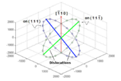
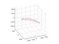
from ![[\,-\pi,\,\pi\,]](/mediawiki/images/math/c/b/f/cbf90b754f2f5e7b11f182d46c0c3ce7.png) generates a circle on the glide plane. We have chosen to do 20 evenly distributed line orientations for both dislocations in this study. This results in a discretization for both dislocations shown in Figure 1, where the points represent the initial line direction.
generates a circle on the glide plane. We have chosen to do 20 evenly distributed line orientations for both dislocations in this study. This results in a discretization for both dislocations shown in Figure 1, where the points represent the initial line direction.
% Make dislocations
t = [-1:0.1:1]*pi;
%Creates dislocations on [1 1 1]
x = 2000*(-cos(t)/sqrt(2)-sin(t)/sqrt(6));
y = 2000*(cos(t)/sqrt(2)-sin(t)/sqrt(6));
z = 2000*(2*sin(t)/sqrt(6));
%Creates dislocations on [1 1 -1]
x1 = 2000*(-cos(t)/sqrt(2)+sin(t)/sqrt(6));
y1 = 2000*(cos(t)/sqrt(2)+sin(t)/sqrt(6));
z1 = 2000*(2*sin(t)/sqrt(6));

%%Plots orientation circle plot seen in the Wiki
%figure(2)
%plot3(x,y,z,'-o', x1,y1,z1,'-o');
%xlim([-2500 2500]);ylim([-2500 2500]);zlim([-2500 2500]);
%grid on
%view([30 -30 40]);
Junction Length Calculation
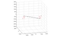
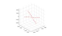
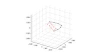
The length of the dislocation junction along the line of intersection is thought to be related to the strength of the Lomer-Cottrell lock. Therefore, we desire to calculate the junction length after the dislocations have been allowed to relax. We also want this calculation to be automated, because we hope to simulate 441 configurations. It is obvious from Figure 2 that the nodes at the ends of this "zipped" junction are unique in that they possess more than two arms. Calculating the length of the junction is as simple as finding the magnitude of the vector between the two free nodes possessing three or more arms from the first column of the linksconnect matrix. However, if the dislocations are oriented in such a way that junction formation is unfavorable, they could remain crossed at a single point, as illustrated in Figure 3. If there is less than two free nodes with three or more arms, then the junction length is zero. A simple algorithm in MATLAB is:
 inter_nodes = find(-10^-2<rn(:,3) & rn(:,3)<10^-2 );
 inter_nodes_seg = connectivity(inter_nodes,1);
 junc_end_nodes= find(inter_nodes_seg>2);
 if length(junc_end_nodes)<2
   junc_length(dis1_no,dis2_no)=0;
 else
   junc_length(dis1_no,dis2_no)=norm(inter_coord(junc_end_nodes(1),1:3)...
   -inter_coord(junc_end_nodes(2),1:3));
 end
This algorithm works when the dislocations have only partially zipped a junction, which encompasses the majority of situations. However, if one of the dislocations is in the ![[\,1\,\bar{1}\,0\,]](/mediawiki/images/math/d/7/8/d789ca1d2ca340ca4fe1db1e7b164668.png) or
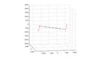
or ![[\,\bar{1}\,1\,0\,]](/mediawiki/images/math/2/3/f/23f9693c849c84fbdb20f3ac27ede1b7.png) direction, it is coincident with the intersection line and, thus, the dislocations have the possibility to fully zip the junction, as shown in Figure 4. In these situations a fixed end node is also the end node of the zipped junction. The end nodes of the junction now only possess two arms, because the fixed nodes were placed at the end of the dislocation. Therefore, the aforementioned algorithm would find the junction length to be zero, rather than the entire length of the original dislocation (4000). Since the fixed nodes possess a flag in rn, a simple improvement to the previous algorithm is:
direction, it is coincident with the intersection line and, thus, the dislocations have the possibility to fully zip the junction, as shown in Figure 4. In these situations a fixed end node is also the end node of the zipped junction. The end nodes of the junction now only possess two arms, because the fixed nodes were placed at the end of the dislocation. Therefore, the aforementioned algorithm would find the junction length to be zero, rather than the entire length of the original dislocation (4000). Since the fixed nodes possess a flag in rn, a simple improvement to the previous algorithm is:
 fixed_nodes = find(rn(:,4)~=0);
 inter_fixed_nodes = find(inter_coord(:,4)~=0);
 ...
 inter_nodes_seg(inter_fixed_nodes)=inter_nodes_seg(inter_fixed_nodes)+1;
This would add one to the connectivity of the end nodes such that the value of a zipped end node is three, which is detected as a junction end node.
Unfortunately, this algorithm still fails to address when both dislocations overlap, i.e. they both lie along the intersection line. We know physically that the dislocations would combine to form a single dislocation if they are attractive. This is exactly what will happen in the simulations, because DDLab and ParaDiS both handle topological changes. Therefore, this junction length should be considered the entire length of the dislocation, but the previous algorithm would find it to be zero, because there are no nodes with more arms than they originally possessed. However, when the dislocations are repulsive the results in DDLab do not correspond to reality. The dislocations are not able to simply move apart, because their end nodes are pinned. The DDLab results for this situation can be seen in Figure 5. In this case, only the end nodes will merge. An entirely different approach must be used to calculate junction length for these special cases. Initially, rn had four fixed nodes with a flag of 7; after the topological changes, there are only two fixed nodes, which is unique to these scenarios. In the case of repulsion the fixed nodes have two arms, while they only have one in attraction. These additions can be seen in LC_junction.m
Batch Execution
Executing a batch of 441 jobs in DDLab is as simple as generating a matrix with all the positions of the dislocation on the  and another for the one on
  , as explained in the Initial Orientation Section and accomplished in make_dis.m. These matrices can then be used with a standard input deck with a set of loops as seen in LC_junction.m. The junction length of each iteration is stored in the matrix junc_length
Resolved Shear Stress Calculation
After, the dislocations are allowed to relax and form junctions. A shear stress is applied on the  plane in order to determine the resolved shear stress necessary to break the junction. Thus far, we have been using the Cartesian coordinate system with basis
 ![\mathbf{e_1}=[\,1\,0\,0\,]](/mediawiki/images/math/0/0/6/00612432e590f9accd9a4ec7c2af1e38.png) ,
, ![\mathbf{e_2}=[\,0\,1\,0\,]](/mediawiki/images/math/c/0/a/c0a2229618980e3a3037a368cc59fa0a.png) , and
, and ![\mathbf{e_3}=[\,0\,0\,1\,]](/mediawiki/images/math/b/3/c/b3cab7632b3a9103e0a6687270275dec.png) . A stress transformation is needed in order to apply the shear directly on the
. A stress transformation is needed in order to apply the shear directly on the  plane. The new orthogonal coordinate system was chosen as
 ![\mathbf{e_1'}=[\,\bar{1}\,\bar{1}\,2\,]](/mediawiki/images/math/7/5/2/752e814f045c0395dce82ff986b47fda.png) ,
, ![\mathbf{e_2'}=[\,\bar{1}\,1\,0\,]](/mediawiki/images/math/a/4/4/a4418043b0ead75354c0d1350bf7ab53.png) , and
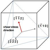
, and ![\mathbf{e_3'}=[\,\bar{2}\,\bar{2}\,\bar{2}\,]](/mediawiki/images/math/d/a/1/da1b9002b8358807ec6c490a06360623.png) , as illustrated in Figure 6.
, as illustrated in Figure 6.
The stress transformation can be performed by the relation,:

where  and
and  are the stress tensor defined in the original and new coordinate systems.
  is the transformation matrix, where the columns of
  are the components of the basis
  written in terms of the basis
  . If
. If  and
and  are chosen as orthonormal bases, then
  is an orthogonal matrix consisting of directional cosines, and
  equals
  .
.
%stress in coordinate system 2
sigma = [ 0    0  0.6
          0    0  0
          0.6  0  0 ] * 1e8;   %in Pa

%coordinate system 1
e1 =  [-1 -1 2]; e2  = [-1 1 0]; e3 = [-2 -2 -2];
e1=e1/norm(e1); e2=e2/norm(e2); e3=e3/norm(e3);

%coordinate system 2 (cubic coordinate system)
e1p = [1 0 0]; e2p = [0 1 0]; e3p = [0 0 1];
e1p=e1p/norm(e1p); e2p=e2p/norm(e2p); e3p=e3p/norm(e3p);

%rotation matrix
Q = [ dot(e1,e1p) dot(e2,e1p) dot(e3,e1p)
      dot(e1,e2p) dot(e2,e2p) dot(e3,e2p)
      dot(e1,e3p) dot(e2,e3p) dot(e3,e3p) ];

%Transform stress tensor into coordinate system 1
appliedstress = Q*sigma*Q'
Description of Files
This section provides a brief description of all the files used in this tutorial and their heirarchy. The main bullets are the primary scripts, and the sub-bullets are the functions or scripts they call.
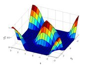
- LC_Junction.m- This script calculates the length of the junction formed between the two dislocations in the absence of stress, as described in the Junction Length Calculation section. It generates the surface plot of normalized junction length as a function of orientation shown in Figure _____. It stores the final dislocation data and junction length (rn, links, and junc_length) in LC_junction_data.mat.
- LC_make_dis.m- The script that generates the coordinate of one fixed node for all 21 initial orientations of both dislocations from -\pi to \pi. The midpoint of all the dislocations is the origin
- LC_relax.m- Script with the input deck for DDLAB with zero applied stress. It requires D1 and D2, one fixed node position for dislocations 1 and 2 respectively; and dis_length, the initial length of the dislocations, as inputs.
- LC_junc_length.m- Function that calculates the length of the resulting binary junction. It takes the resulting rn and connectivity matrices from LC_relax.m as inputs and returns only junction length.
- LC_dissociate.m- This script determines the critical stress to dissociate a binary junction based on the orientation of the dislocations. The orientation angle of dislocation 1,
 , equals
  and those of dislocation 2,
 , are
, are  ,
,  , and
, and  . The junction data is loaded from LC_junction_data.mat. The user inputs a guess at the critical shear stress in coordinate system 2 (see the Resolved Shear Stress Calculation section). The resulting cricitical shear stresses are plotted with φ2 and junction length. It is best to start with a conservative guess to avoid having the dislocations dissociate and begin acting as Frank-Read sources, which is costly computationally.
- LC_stress.m- Script with the DDLAB input deck for the user specified
 in coordinate system 2. It performs the stress transformation described in the Resolved Shear Stress Calculation section. It also requires that dis_length, the initial length of the dislocations prior to junction formation, is specified.
- LC_stress.m- Script with the DDLAB input deck for the user specified
- LC_length.m- This script determines the critical stress to dissociate a binary junction based on the initial length of the dislocations.
 and
and  are both chosen as
  . The user inputs a guess at the critical shear stress in coordinate system 2 (see the Resolved Shear Stress Calculation section). The resulting critical shear stresses are plotted with junction length.
- LC_relax.m- See above.
- LC_junc_length.m- See above.
- LC_stress.m-See above.
Results and Conclusions
References
<references/>
