Work in Progress
Until this page is finished please refer to Media:LC_lock.pdf. Note: There are some errors associated with the junction length calculation in the code provided. These have been addressed and will be corrected in the forthcoming guide on this page.
Contents |
Introduction
This tutorial will:
- Study the formation and dissociation of Lomer-Cottrell (binary) junctions in fcc crystals using both DDLab and ParaDiS
- Introduce running a batch of simulations, and calculating junction length and critical resolved shear stress to cause dissociation of the junction
- Determine the dependence of junction length and critical stress on the initial orientation of the intersecting dislocations
- Illustrate the mobility of nodes at the intersection of glide planes in DDLab and ParaDiS
- Discuss any limitations. Physically the junction should be sessile. But in the simulation, the inner nodes of the junction segment are able to move. The end nodes of the junction are confined to the intersection line as they should.
This tutorial assumes that the reader is familiar with the basics of DDLAB. New users should read DDLab_Manual_01 before proceeding.
A copy of the input decks used in this tutorial can be downloaded from the link at the bottom of this page.
Background
Plastic deformation of metals is usually governed by the motion of dislocations and their reactions, such as nucleation, pinning, and multiplication. One particularly important interaction occurs when two dislocations on different glide planes approach each other. These dislocations could either repel or attract each other depending on their Burgers vectors and orientations. If they are pulled together, the dislocations will combine in a way that minimizes their energy. This often results in the "zipping" of the dislocations along the line of intersection of the glide planes to form a junction known as a Lomer-Cottrell lock. These junctions have been shown to be a governing cause of strain hardening in fcc crystals.
Simulation Design
Initial Orientation
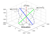
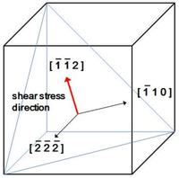
In order to simplify the simulations, two dislocations with identical lengths, but on differing slip planes, are initially placed such that they intersect at their center. The dislocations glide on the  and
and  planes, respectively, which are part of the
  slip system in fcc crystals. A Lomer-Cottrell junction could form at the intersection of these two planes, i.e. along the
 ![[\,\bar{1}\,1\,0\,]](/mediawiki/images/math/2/3/f/23f9693c849c84fbdb20f3ac27ede1b7.png) direction, if the conditions are correct.
direction, if the conditions are correct.
Mathematically, we can make a circle by a parametric representation form. If the  is the parameter and the point
  on the circle is given by:

where  is the location of the center of the circle
 is a unit vector from the center of the circle toward the point; R is the radius; and
  is a unit vector perpendicular to the plane containing the circle. Here, for two dislocations, the normal vectors,
  , are
, are ![[\,1\,1\,1\,]](/mediawiki/images/math/b/6/8/b68cf48ced06b1c14ad65cb398195b89.png) and
and ![[\,1\,1\,\bar{1}\,]](/mediawiki/images/math/f/5/5/f55ff662e0d18324b7700ffbfa882ef5.png) , respectively. For simplicity, the dislocations are made to intersect at the origin, thus,
, respectively. For simplicity, the dislocations are made to intersect at the origin, thus,  .
.  is defined the angle between the dislocation and the line of intersection. Therefore,
  is taken as
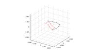
 ![[\,1\,\bar{1}\,0\,]](/mediawiki/images/math/d/7/8/d789ca1d2ca340ca4fe1db1e7b164668.png) . This allows us to construct the circles shown Fig ____, where the 20 points on a circle correspond to the initial orientations of the dislocation in that plane to be simulated. This is done using the following MATLAB code (part of make_dis.m):
. This allows us to construct the circles shown Fig ____, where the 20 points on a circle correspond to the initial orientations of the dislocation in that plane to be simulated. This is done using the following MATLAB code (part of make_dis.m):
 t = [-1:0.1:1]*pi;
 x = 2000*(-cos(t)/sqrt(2)-sin(t)/sqrt(6));
 y = 2000*(cos(t)/sqrt(2)-sin(t)/sqrt(6));
 z = 2000*(2*sin(t)/sqrt(6));

 x1 = 2000*(-cos(t)/sqrt(2)+sin(t)/sqrt(6));
 y1 = 2000*(cos(t)/sqrt(2)+sin(t)/sqrt(6));
 z1 = 2000*(2*sin(t)/sqrt(6));

 figure(2)
 plot3(x,y,z,'-o', x1,y1,z1,'-o');
 xlim([-2500 2500]);ylim([-2500 2500]);zlim([-2500 2500]);
 grid on
 view([30 -30 40]);
Junction Length Calculation
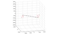
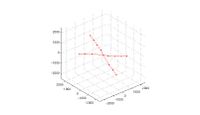
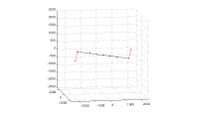
The length the dislocation junction along the line of intersection is thought to be related to the strength of the Lomer-Cottrell lock. Therefore, we desire to calculate the junction length after the dislocations have been allowed to relax. It is obvious from Fig. _____ that the nodes at the ends of this "zipped" junction are unique in that they possess more than two arms. Calculating the length of the junction is as simple as finding the magnitude of the vector between the two free nodes possessing three or more arms from the first column of the linksconnect matrix. However, if the dislocations are oriented in such a way that junction formation is unfavorable, they could remain crossed at a single point, as illustrated in Fig. ______. If there is less than two free nodes with three or more arms, then the junction length is zero. A simple algorithm in MATLAB is:
 inter_nodes = find(-10^-2<rn(:,3) & rn(:,3)<10^-2 );
 inter_nodes_seg = connectivity(inter_nodes,1);
 junc_end_nodes= find(inter_nodes_seg>2);
 if length(junc_end_nodes)<2
   junc_length(dis1_no,dis2_no)=0;
 else
   junc_length(dis1_no,dis2_no)=norm(inter_coord(junc_end_nodes(1),1:3)...
   -inter_coord(junc_end_nodes(2),1:3));
 end
This algorithm works in the majority of situations...
