To simplify the discussion, let us use $ParaDiS to represent the directory where you ParaDiS code is installed. For example, on my computer, $ParaDiS is ~/Codes/ParaDiS.
I have the following subdirectory within $ParaDiS that holds my DDLab files.
$ParaDiS/Matlab/dd3d
In this test case, I will illustrate how to convert DDLab control parameters and dislocation structures into .cn and .data files that can be recognized by ParaDiS. It assumes that the DDLab is installed in a subdirectory of ParaDiS as described above.
In Matlab, first go to your DDLab directory. Then set up the initial structure for a binary junction by
cd Inputs; input_binary_junction; cd ..
You can run this test case in Matlab by simply typing
dd3d
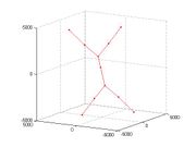
which will show the formation of a junction (after the 200 simulation steps as specified by the input file).
Suppose we now want to run the same simulation in ParaDiS. We need to re-run the input file and then ask Matlab to write the data into ParaDiS format. This can be done by the following command.
cd Inputs; input_binary_junction; cd ..
write_paradis_input
The computer will print out the following information.
ParaDiS input file ../../Runs/matlab_input.cn created.
ParaDiS node data file ../../Runs/matlab_input.data created.
The two files are created in the ../../Runs directory, which is specified by the matlab variable paradis_input_dir. This variable is specified in the input_binary_junction.m file.
In your Unix (or cygwin) terminal, go to the $ParaDiS directory. Suppose you have compiled the source code and have the dd3d executable see here. You can run the input files created by DDLab using the following command.
./dd3d Runs/matlab_input.cn
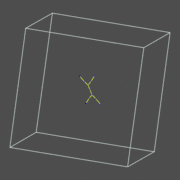
You should see the formation of junction in the X-window of ParaDiS.
You are certainly able to modify (or rename) the input files created by DDLab before running ParaDiS. The .cn file and the .data file must have the same name.

