PARADISCYL:How-To-Get-Nodal-Force: Difference between revisions
mNo edit summary |
|||
| (2 intermediate revisions by one other user not shown) | |||
| Line 3: | Line 3: | ||
How to get nodal force</H1> |
How to get nodal force</H1> |
||
<DIV> |
<DIV> |
||
This document describes the extension of the ParaDiS program that implements the cylindrical free surface boundary condition. This extension is based on Weinberger and Cai, J. Mech. Phys. Solids, 55, 2027 (2007)([http://micro.stanford.edu/~caiwei/papers/Weinberger07jmps-image.pdf PDF]). The code is written by Chris Weinberger and Wei Cai and is not included in the standard distribution of ParaDiS. Keonwook Kang wrote the first draft of this document, which was later revised by Chris Weinberger and Wei Cai. Questions on this document should be addressed to [[Chris Weinberger]]. Please read the manual of ParaDiS before reading this document. |
|||
== Motivation == |
|||
In ParaDiS, a dislocation line is represented by piecewise straight segments connecting a set of discrete nodal points. For diagnostic purposes, we may want to find out the driving force on every node. Here we explain how to extract this information from the ParaDiS Cylinder code. |
In ParaDiS, a dislocation line is represented by piecewise straight segments connecting a set of discrete nodal points. For diagnostic purposes, we may want to find out the driving force on every node. Here we explain how to extract this information from the ParaDiS Cylinder code. |
||
Latest revision as of 17:04, 27 October 2008
Manual 04 for ParaDiS Cylinder Codes
How to get nodal force
This document describes the extension of the ParaDiS program that implements the cylindrical free surface boundary condition. This extension is based on Weinberger and Cai, J. Mech. Phys. Solids, 55, 2027 (2007)(PDF). The code is written by Chris Weinberger and Wei Cai and is not included in the standard distribution of ParaDiS. Keonwook Kang wrote the first draft of this document, which was later revised by Chris Weinberger and Wei Cai. Questions on this document should be addressed to Chris Weinberger. Please read the manual of ParaDiS before reading this document.
Motivation
In ParaDiS, a dislocation line is represented by piecewise straight segments connecting a set of discrete nodal points. For diagnostic purposes, we may want to find out the driving force on every node. Here we explain how to extract this information from the ParaDiS Cylinder code.
Computing nodal force
Modify makefile in ParaDiS/cylinder directory so that the following line is active.
DEFS += -D_WRITENODEFORCE
Then compile ParaDiS cylinder codes again.
Next, run the executable with the input file, such as that in M02 Test Run,
$ bin/paradiscyl runs/concentric_loop_test.ctrl.
Note that, even if the total simulation step is set as 100 in the control file, the ParaDiS simulation does one time force evaluation and will quit immediately afterwards.
The force data is dumped out as force.out in the outputs/concentric_loop_test/ directory. Each line of this file has 6 values for nodal point coordinate (x, y, z) and nodal force components (fx, fy, fz), respectively.
Because the default stress unit is Pa and length unit is burgMag, the unit of nodal forces is Pa.burgMag^2. Of course, this is the case for cylinder radius R = 1. If we want to interprete the results for the case of R not equal to one, then the force will have to be scaled according to M03 How units are scaled.
Plotting nodal force

Nodal force with all image stress considered
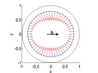
Nodal force with no BEM image stress
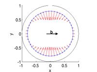
Nodal force with no Yoffe stress


matlab script
%%%%%%%%%%%%%%%%%%%%%%%%%%%%%%%%%%%%%%%%%%%%%%%%%%%%%%%%%
% plot node force
%
% outdir : directory where nodal force data file is dumped out.
% nodalforcefilename : file name of nodal force data

outdir = '~/Codes/ParaDiS/outputs/concentric_loop_test/';
nodalforcefilename = 'force.out';

fullname_nodalforcefile = sprintf('%s%s',outdir,nodalforcefilename);

data = load(fullname_nodalforcefile);

node_position = data(:,1:3);
nodal_force = data(:,4:6);

%%%%%%%%%%%%%%%%%%%%%%%%%%%%%%%%%%%%%%%%%%%%
% cylinder geometry
r = 1;
theta = linspace(0,2*pi,100);
z = 0;
[x,y,z] = pol2cart(theta,r,z);


figure(1), set(gca,'fontsize',20), hold on
plot(x,y,'-k')                                      % plot cylinder
plot3([node_position(:,1);node_position(1,1)],...   % plot dislocation loop
      [node_position(:,2);node_position(1,2)],...
      [node_position(:,3);node_position(1,3)],'.-')
quiver3(node_position(:,1),node_position(:,2),node_position(:,3),...
        nodal_force(:,1),nodal_force(:,2),nodal_force(:,3),1,'r')
text('position',[0 .07 0],'string','b','fontsize',20,'fontweight','bold')
annotation('arrow', [0.48 0.60],[0.53 0.53],...
           'LineWidth',3,'HeadStyle','plain','HeadWidth',12,'HeadLength',12);
xlabel('x'), ylabel('y')
view(2), axis equal, axis([-1 1 -1 1])
hold off