PARADISCYL:How-To-Get-Nodal-Force: Difference between revisions
| Line 39: | Line 39: | ||
== Plotting nodal force == |
== Plotting nodal force == |
||
<gallery widths="200px" heights="200px" perrow="3"> |
|||
[[image:Nodalforce1.jpg | 300px]] |
|||
Image:Nodalforce1_v2.jpg |Nodal force with all image stress considered |
|||
Image:Nodalforce2.jpg |Nodal force with no BEM image stress |
|||
Image:Nodalforce3.jpg |Nodal force with no Yoffe stress |
|||
</gallery> |
|||
matlab script |
matlab script |
||
| Line 74: | Line 78: | ||
quiver3(node_position(:,1),node_position(:,2),node_position(:,3),... |
quiver3(node_position(:,1),node_position(:,2),node_position(:,3),... |
||
nodal_force(:,1),nodal_force(:,2),nodal_force(:,3),1,'r') |
nodal_force(:,1),nodal_force(:,2),nodal_force(:,3),1,'r') |
||
text('position',[0 .07 0],'string','b','fontsize',20,'fontweight','bold') |
|||
annotation('arrow', [0.48 0.60],[0.53 0.53],... |
|||
'LineWidth',3,'HeadStyle','plain','HeadWidth',12,'HeadLength',12); |
|||
xlabel('x'), ylabel('y') |
|||
view(2), axis equal, axis([-1 1 -1 1]) |
view(2), axis equal, axis([-1 1 -1 1]) |
||
hold off |
hold off |
||
Revision as of 07:58, 3 October 2008
Manual 03 for ParaDiS Cylinder Codes
How to get nodal force
Keonwook Kang and Wei Cai
Overview
In ParaDiS, a dislocation is idealized as a piecewise line object: discrete nodal points and lines connecting them. Sometimes, we need to know how much force is acting on each node under given dislocation geometry. In this manual, it will be explained how we export nodal force data from ParaDiS simulation.
Procedure
Modify makefile in ParaDiS/cylinder directory such that DEFS macro include definition of WRITENODEFORCE or
DEFS += -D_WRITENODEFORCE
Then compile ParaDiS cylinder codes again.
Let's say we want to know nodal forces of a dislocation loop inside a cylinder used in test simulation run. Run the control file, runs/concentric_loop_test.ctrl.
$ bin/paradiscyl runs/concentric_loop_test.ctrl.
Note that, even if the total simulation step is set as 100 in the control file, the ParaDiS simulation does one time force evaluation and will quit after then.
You will see that the force data is dumped out as force.out in outputs/concentric_loop_test/ directory. Each line of the force data file has 6 numbers of nodal point coordinate (x, y, z) and nodal force components (fx, fy, fz).
(What is the unit of force???)
Plotting nodal force

Nodal force with all image stress considered
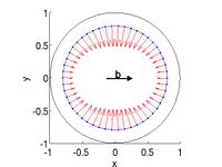
Nodal force with no BEM image stress
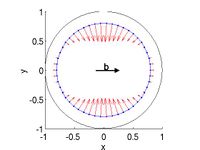
Nodal force with no Yoffe stress


matlab script
%%%%%%%%%%%%%%%%%%%%%%%%%%%%%%%%%%%%%%%%%%%%%%%%%%%%%%%%%
% plot node force
%
% outdir : directory where nodal force data file is dumped out.
% nodalforcefilename : file name of nodal force data

outdir = '~/Codes/ParaDiS/outputs/concentric_loop_test/';
nodalforcefilename = 'force.out';

fullname_nodalforcefile = sprintf('%s%s',outdir,nodalforcefilename);

data = load(fullname_nodalforcefile);

node_position = data(:,1:3);
nodal_force = data(:,4:6);

%%%%%%%%%%%%%%%%%%%%%%%%%%%%%%%%%%%%%%%%%%%%
% cylinder geometry
r = 1;
theta = linspace(0,2*pi,100);
z = 0;
[x,y,z] = pol2cart(theta,r,z);


figure(1), set(gca,'fontsize',20), hold on
plot(x,y,'-k')                                      % plot cylinder
plot3([node_position(:,1);node_position(1,1)],...   % plot dislocation loop
      [node_position(:,2);node_position(1,2)],...
      [node_position(:,3);node_position(1,3)],'.-')
quiver3(node_position(:,1),node_position(:,2),node_position(:,3),...
        nodal_force(:,1),nodal_force(:,2),nodal_force(:,3),1,'r')
text('position',[0 .07 0],'string','b','fontsize',20,'fontweight','bold')
annotation('arrow', [0.48 0.60],[0.53 0.53],...
           'LineWidth',3,'HeadStyle','plain','HeadWidth',12,'HeadLength',12);
xlabel('x'), ylabel('y')
view(2), axis equal, axis([-1 1 -1 1])
hold off